| In previous
chapters, we discussed how thermostats worked to control the flow of coolant
between the engine and the radiator. In this discussion, we will discuss
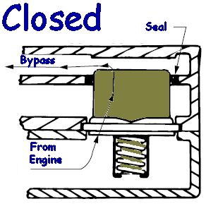
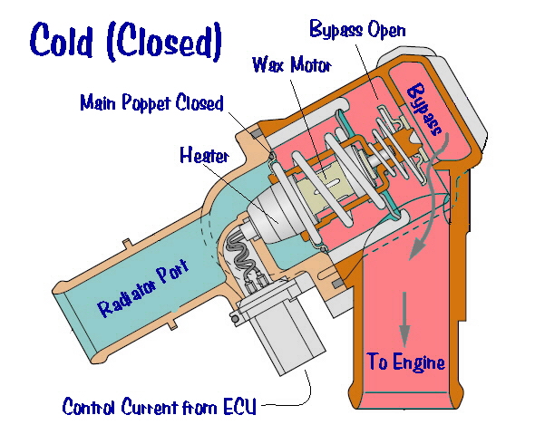
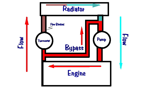
what happens when the thermostat is closed, blocking the path to the radiator.
Bypass
History
In the
beginning...
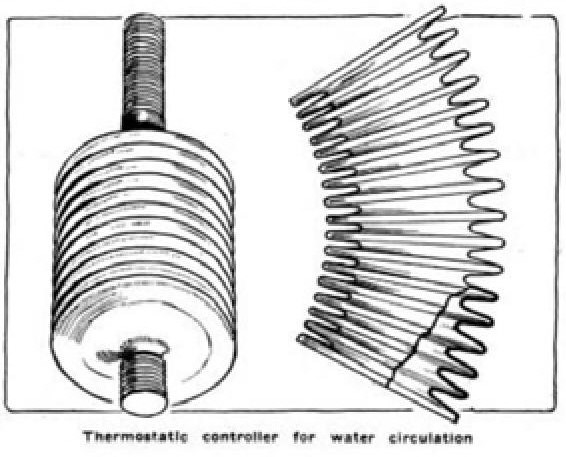
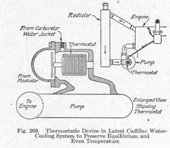
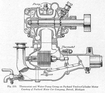
The bypass in this early Cadillac comprised a small tube leading from the carburetor water jacket to the pump inlet. This was sufficient to provide some circulation when the thermostat was closed, the clear intent being to encourage fuel vaporization. However, the open bypass was not designed to limit flow when the thermostat was open. As a result, some hot coolant always recirculated through the bypass line. The only limitation on the volume of recirculated coolant was the small diameter of the tube. Although somewhat primitive, this thermostat and bypass system allowed the Cadillac engine to develop an enduring reputation for reliability and economy which proved to be the foundation of the brand. Not to be outdone, Packard's V12, introduced in the Spring of 1915, incorporated a Sylphon bellows unit which controlled both a primary valve and a bypass valve:
The Packard engine, like the Jaguar V12, was essentially two six cylinder engines built on a common crank. Each bank had it's own water pump and thermostat, so the Packard was prone to some of the same problems as the Jag. The Sylphon bellows was still not built into a self contained thermostat, but operated a bellcrank system on which two butterfly valves were mounted, one controlling the bypass and one controlling the radiator passage. This allowed full volume bypass circulation, a big improvement over the Cadillac system. Thermal control was comparable to a modern engine. Gestation
By 1930, two events came together to advance cooling system design. The first was the development of the self contained cartridge thermostat. As we know it today, a brass or stainless thermostat includes the motor, valve, and support structure, and is built as a replaceable assembly. We don't even think of these things as separate parts today, but it was a new idea at the time. The other event was the acquisition of a series of thermostat companies by Reynolds Metals (as in Reynolds aluminum wrap), accompanied by a big sales push. Among the companies absorbed were Fulton Sylphon, Robertshaw, Bridgeport Brass and American Thermostat. A veritable juggernaut of thermal control. These companies would variously operate as independent or combined entities, aggressively dominating the thermostat market for many years. It's a very confusing corporate history. Buick
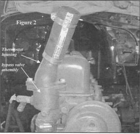
1931
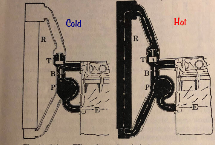
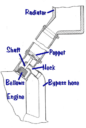
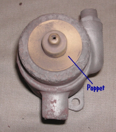
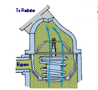
The diagram
is a little unclear, but what's going on is that a single poppet thermostat
(T) controls the water exit to the radiator (R). But a completely separate
spring loaded bypass valve (B) independently controls the bypass. The way
this works is that when the thermostat is closed, it arrests flow, which
creates a local area of high static pressure. This pressure opens the bypass
valve, allowing coolant to recirculate to the pump (P) and back to the
engine (E). When the thermostat is open, static pressure throughout the
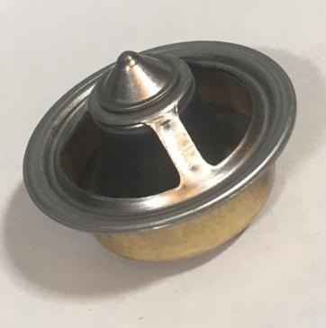
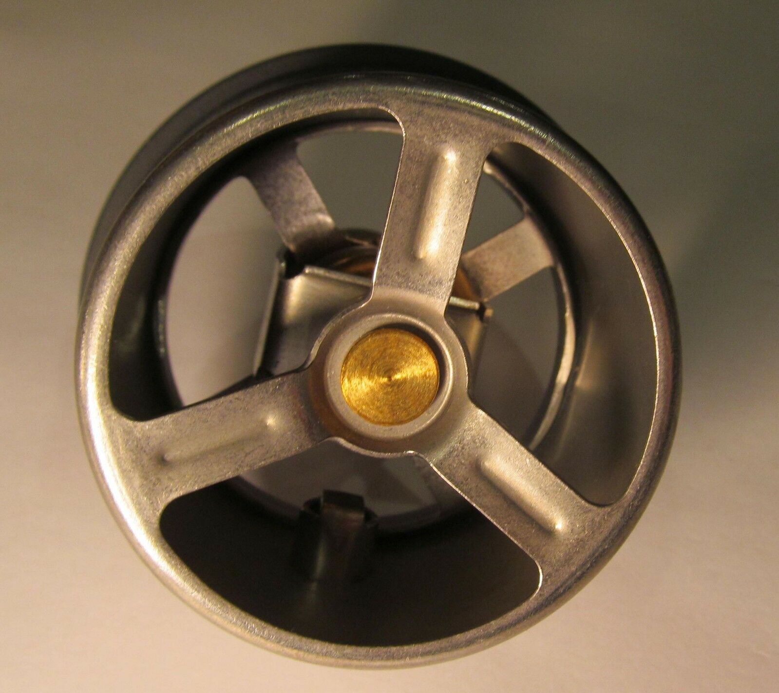
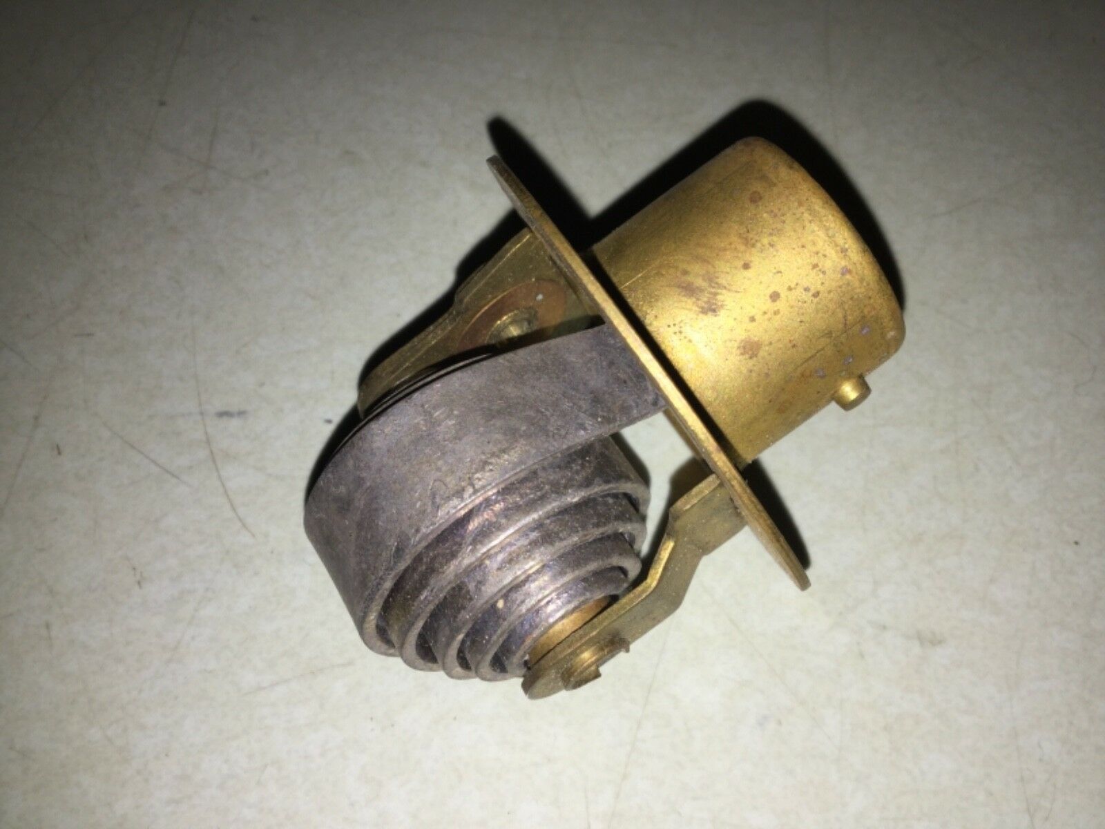
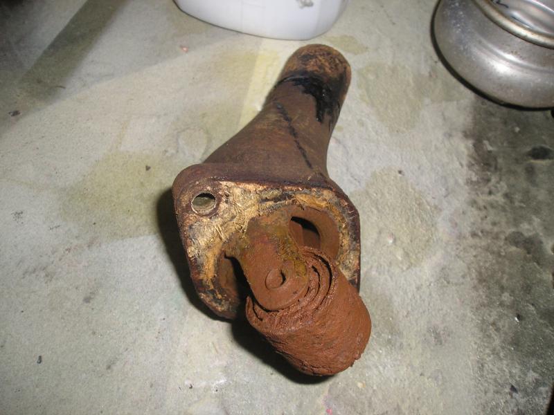
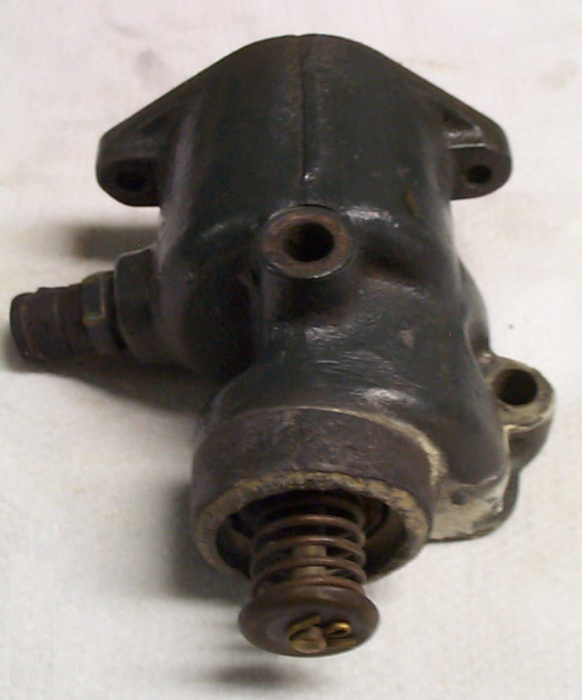
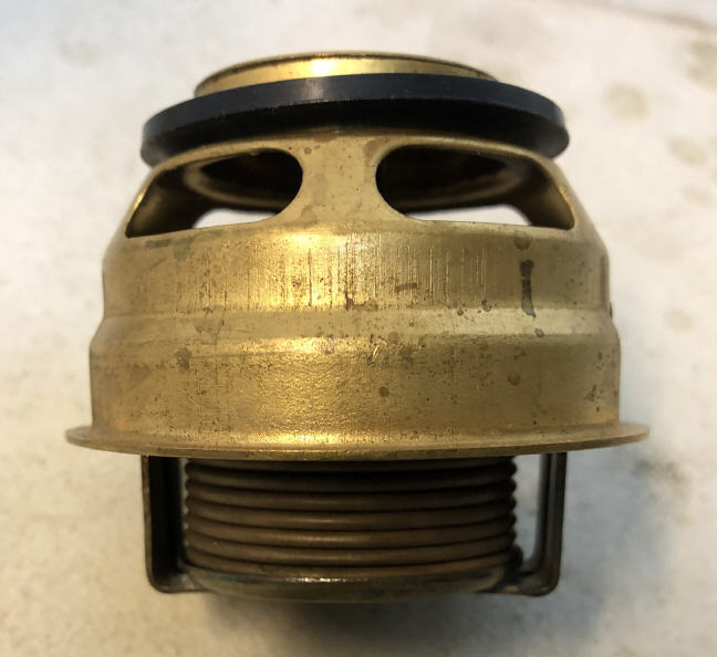
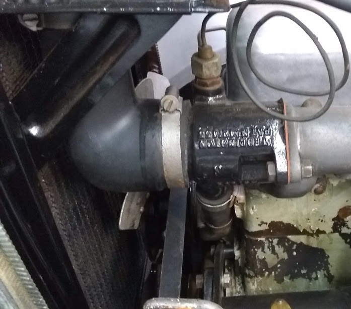
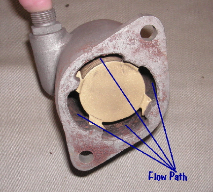
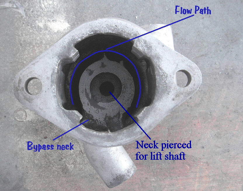
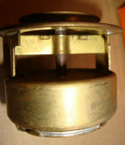
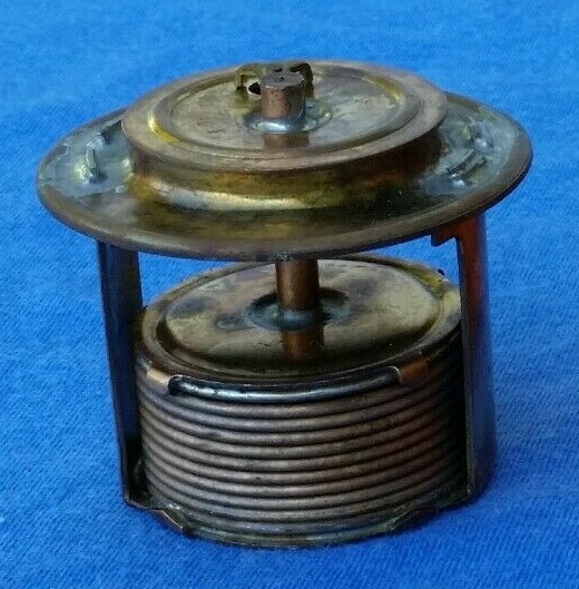
system will be fairly uniform, so the bypass valve closes. Here are
a few photos of the bypass valve:
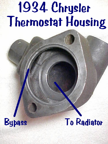
Eventually, this system evolved into the open bypass systems used in most American cars of the 1960's. Open bypass will be discussed in the main chapter on bypass systems. Chrysler
1934
SS Cars
1934
Meanwhile, what was going on in Europe?
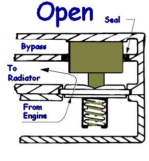
Open bypass systems are typically found in American cars from the late 1950's to the present day. With this system, an unrestricted passage through the head or block routes hot coolant back around to the pump inlet. As the name implies, the bypass passage is always open.
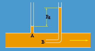
It may
seem as if at least half the coolant will flow through the bypass at all
times. But the physical layout is important. When the thermostat opens,
the dynamic pressure of the fast moving fluid will carry it through the
thermostat. The bypass passage is at right angles to the direction of flow,
and is only exposed to static pressure. Static pressure in the thermostat
capsule will rise if the primary path is obstructed (as with a closed or
partially closed thermostat). Only when this happens will there be flow
through the bypass circuit.
Why doesn't
the open bypass arrangement result in endless recirculation of hot coolant?
Newton's first law of motion. In the absence of interference, inertia carries
the moving coolant through the thermostat. If the primary path is blocked,
energy is conserved and dynamic pressure transforms to a local increase
in static pressure. This forces coolant through the open bypass passage.
The problem with the open bypass system is that there is always some restriction
to the primary flow path. If nothing else, the thermostat itself is a restriction,
even when fully open. As a result, there will always be some undesirable
bypass flow. But not nearly as much as you might expect.
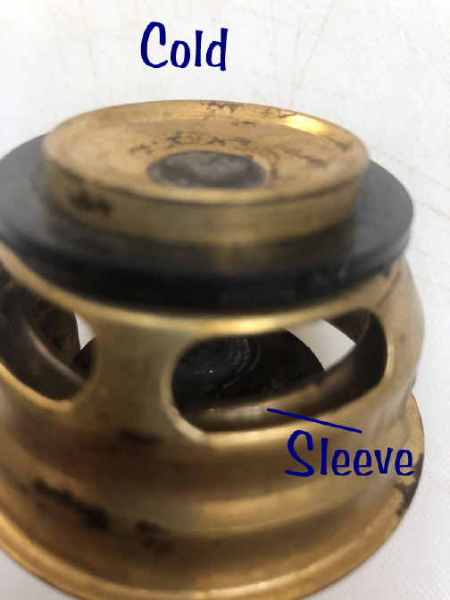
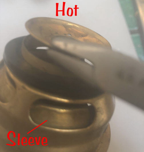
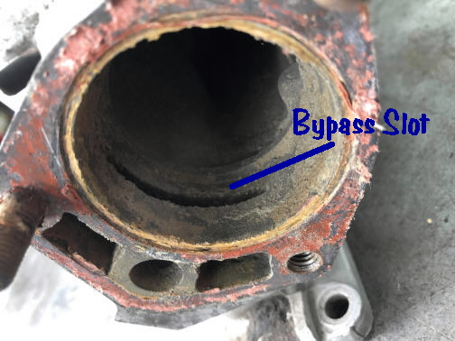
In the 50's, the British motor industry took a different approach to bypass design. Rather than a passive bypass, active control is achieved by a sleeve that is integral to the thermostat poppet. The sleeve controls a bypass slot machined into the side of the the thermostat housing. The sleeve moves with the poppet, and cuts off the bypass as the thermostat opens. Coolant flows at a constant rate, either through the bypass or the main poppet. The thermostat may achieve equilibrium at some partially open position, so flow can be split between the bypass and the radiator to achieve steady head temperature. We'll address specific applications in later chapters.
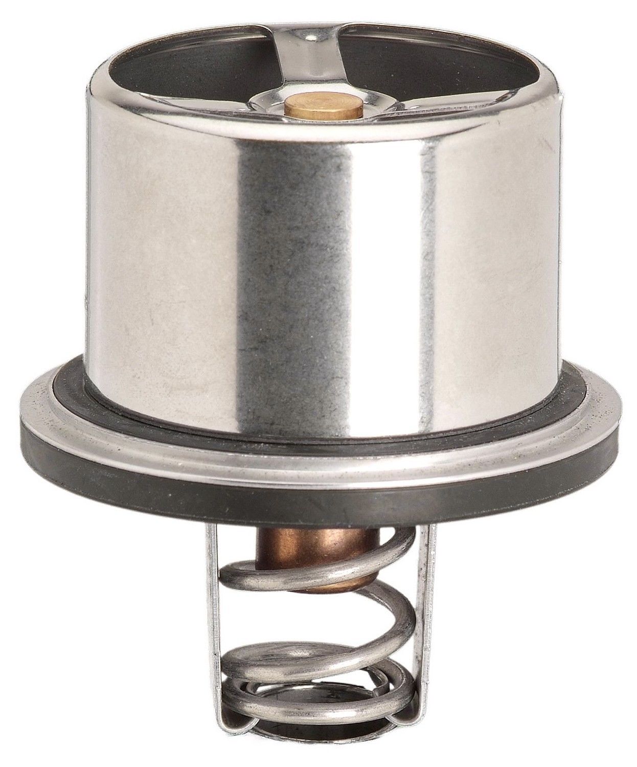
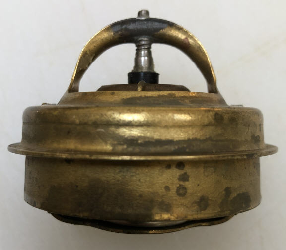
For this
system to operate correctly, a sleeved thermostat must be used. A visual
identification guide:
Advantages:
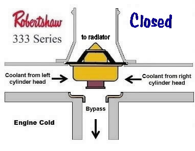
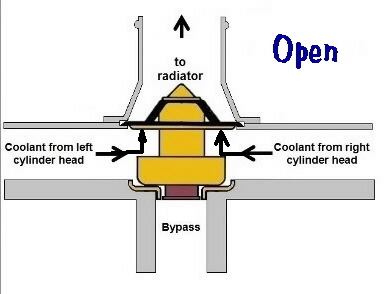
The Ford bypass system is a long digression from the Jaguar story, and will be discussed in greater detail in the section on the 351 Cleveland motor. Very quickly, it uses a unique thermostat originally made by Robertshaw to implement an unsual bypass mechanism. In it's native application, it resides in the intake manifold of a V8, and recieves incoming 'sideways" flow from the two heads. The primary path and the bypass path are at right angles to this flow. Depending on whether the thermostat is open or closed, flow is forced to turn either up into the radiator or down into the bypass passage . In a tribute to the earlier Teddington thermostat, the wax motor itself is used to provide bypass control. This arrangement is discussed here because it's discussed around the web as a solution for slotted bypass applications. It isn't. For now, the important points are that it's based on the Robertshaw 330 thermostat, and that this thermostat Is designed for a very different sort of bypass system.
Advantages:
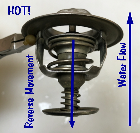
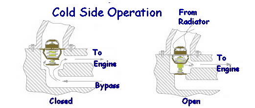
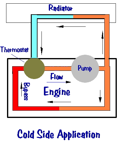
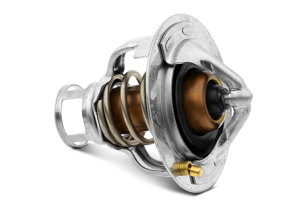
The dual poppet bypass is the most common system used today. There are two poppets mounted to the wax motor, and they both move in the same direction as the thermostat opens. There is a bypass port located parallel to the thermostat flange which is sealed by the lower poppet. This poppet is mounted on a light spring and floats on it's shaft, so that it can automatically adjust to variations in closing distance caused by machining error or wear. 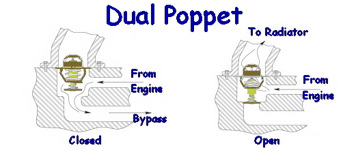 In vintage applications, the thermostat is usually used for "hot side" operation, meaning that its located at the top of the motor, near the water exit. In this location, the wax motor is sensing coolant at the hottest point in the jacket, and will work to keep the exit temperature relatively constant. To complete the discussion of dual poppet thermostats, let's take a quick look at how they work for more modern "cold side" applications. Regulating the temperature of the exit water, as we've seen so far, doesn't directly control variability in the temperature of the inlet water. Some engines are sensitive to thermal shock when cold water enters from the radiator. And all engines benefit by uniform cylinder temperatures for efficiency and emissions. An approach to better thermal control is to make the bypass the primary path, and reverse the flow. This results in hot and cold coolant being blended before being pumped around the engine.
As can
be seen in the diagram, a dual poppet thermostat can be relocated to the
engine inlet simply by moving it to the "bottom" of the engine and reversing
flows. In actual operation, the thermostat is usually somewhere between
closed and open, and the thermostat housing acts as a blending chamber
where cold coolant mixes with hot coolant to keep the entire water jacket
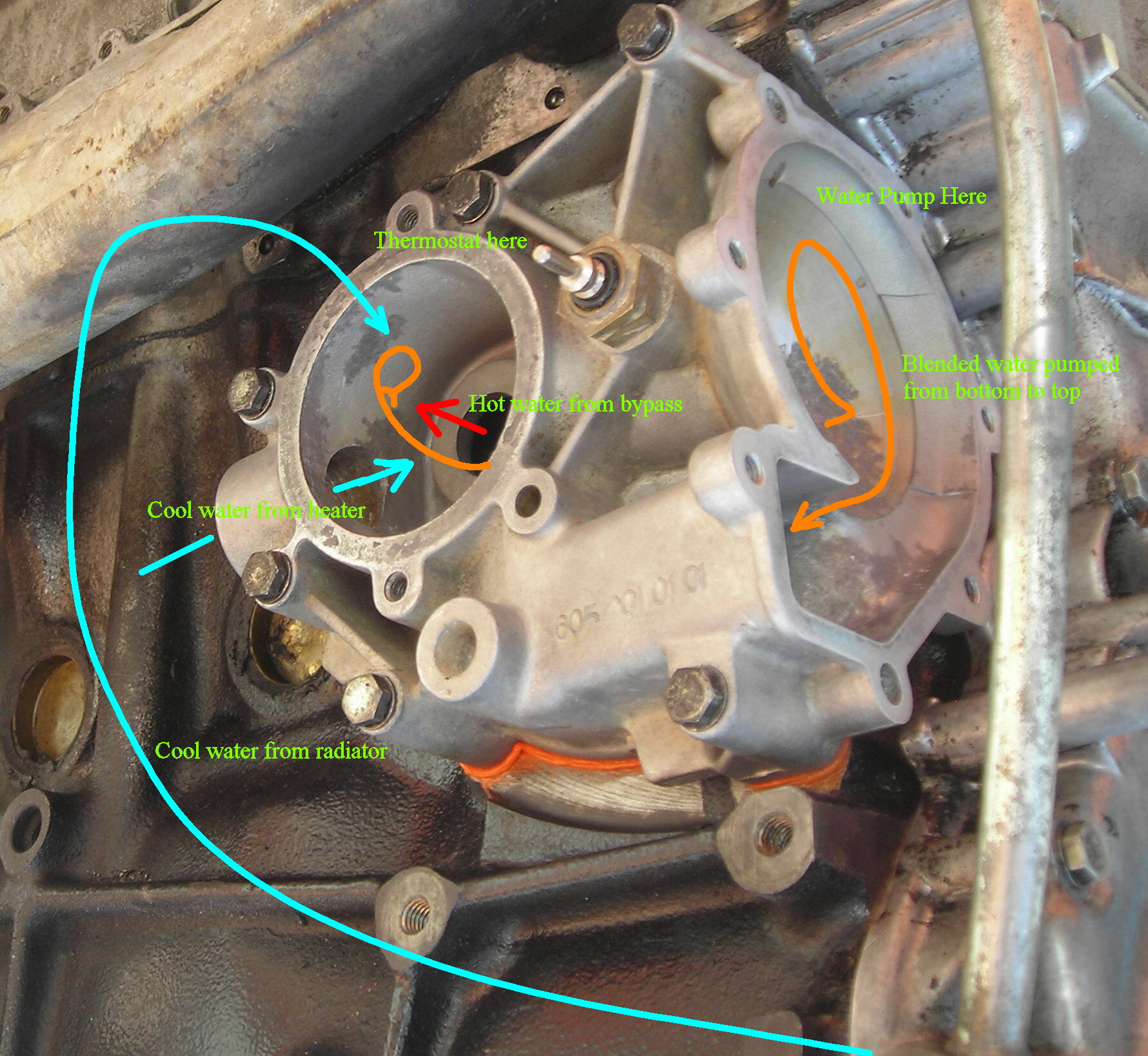
at relatively consistent temperature. Here's a look at a Mercedes cold-side
system. The thermostat chamber acts as the blending point for hot and cold
water before the pump moves it into the block.
Advantages
Another
brief digression here to discuss the high flow systems used for trucks
and heavy duty equipment (and sometimes by BMW.) These are not compatible
with any vintage Jaguar application.
The wax
motor is mounted below the flange, while the sleeve valve sits above the
flange. When hot, motor pushes the sleeve up into the thermostat housing.
Bypass flow is stopped when the sleeve seats in the top of the housing.
This also opens the flow path to the radiator. A positive seal is achieved
by use of o-rings. Note that while it's a balanced force thermostat, because
it is not subject to flow lift.
Advantages
I can't end this chapter without looking at some up-to-date, modern systems. As engines have progressed, so too have thermostats. We earlier said that the purpose of the thermostat was to keep the system warm. But there's complexity to everything. While engine wear becomes acceptable at 160F (70C), the sweet spot for emissions, power or fuel economy can be much higher, up to 230F (110C). What's more, there's no one right answer. The optimal temperature is dependent on transient operating conditions.
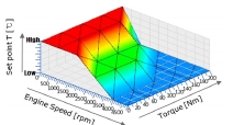
For leading
edge engines, this problem is solved by implementing a thermostat map,
controlled by the engine ECU. In other words, the engine temperature is
varied according to RPM and load under computer control. The mechanism
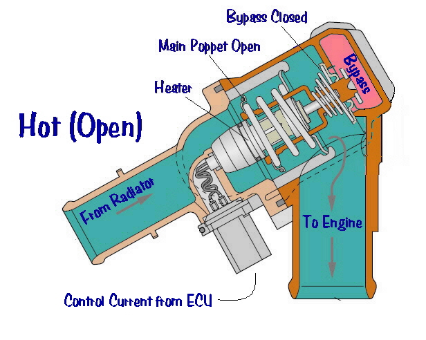
for this is an electronic thermostat:
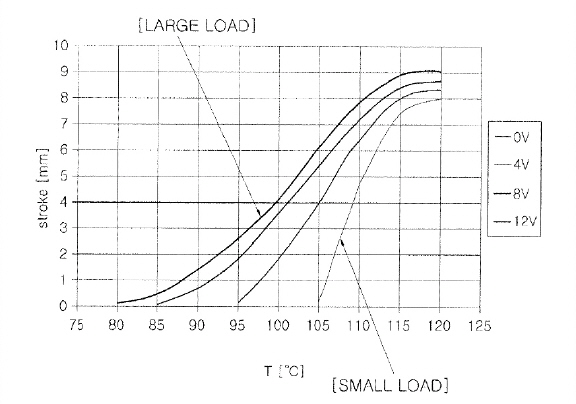
There is still a wax motor. But in this case, the "natural" temperature of the wax motor may be as high as 230F. This set point is a fail-safe, in case the electronics fails. The actual work is done by the ECU. It continuously reads a set of engine sensors, and implements a temperature map by varying the current through the heating coil, which has the effect of shifting the natural thermostat curve.
Advantages
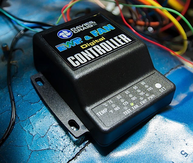
A proposed "future" system is the Davies Craig EWP. This is a combination of an electric fan, electric water pump, temperature sensors, and a digital controller. It uses no thermostat, no mechanical water pump, and no bypass. Instead, the controller cycles an electric water pump on and off as needed. During warm up, it maintains a minimal flow in order to accomplish all the same things as a normal bypass system. Once the engine is warmed up, it increases air and water flow to match engine requirements. Although this is currently being sold as an aftermarket product, it should be considered a half-developed solution.
Advantages
I conclude this chapter with a brief discussion of the most advanced system in use today, the Schaeffler Thermomanagement Module. This system has entered service with some VW/Audi cars. As with the MAP controlled thermostat, the idea is to achieve precise thermal control, matched in real time to driving conditions. But while MAP controlled thermostats build on traditional wax-capsule thermostat technology, the Schaeffler system uses an electronically controlled rotary valve. The advantage is extremely fast warm up, and thermal regulation within ±2c. Rather than attempt to diagram this system, I simply refer my readers to the factory video:
< Air Venting Main S1 E-Type 3.8 > Copyright@2019 CoolCat
Express Corpl
|

 l
l