Relays are widely used in electrical applications where one circuit is to be energized or turned "on" by the presence of a voltage, provided by another circuit. An example of this is when an Otter switch controls a triggering voltage which indicates that the fans should turn on.
The "switch" in a relay is controlled by an electromagnet. The magnet is used to close the switch contacts on the main circuit. The "switch" part of the relay is usually very heavy duty, while the electromagnet draws little current. This allows a very low current signal to control a very high current device. A relay can be triggered with an electrical pulse as small as 150 milliamps. The switched output can be as high as 30 or 40 amps.
Relays can be "normally
closed", "normally open", or both. Normally closed means that when the
magnet isn't energized, the switch contacts are closed, and therefore the
circuit is on. Normally open means the opposite: when the relay isn't energized,
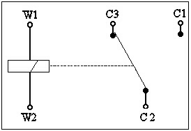
the switch is off. Bosch relays usually have both an "87" and an "87a"
contact, which are respectively NO and NC. This design is also called "single
pole, double throw", or SPDT for short. The following diagram should make
this clearer.
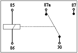
Relay unpowered |
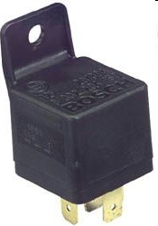
Bosch Relay Base Diagram |
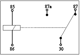
Relay powered |
Connections
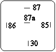
The terminals of a
relay are defined as follows:
|
|
|
|
 |
|
|
|
|
|
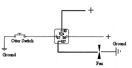 |
| Note: Basic application. |
|
|
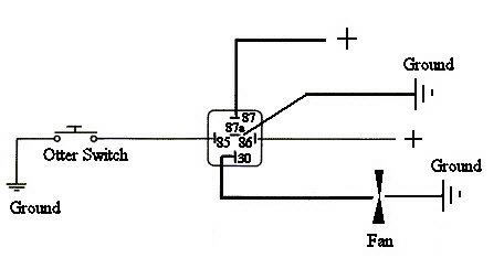 |
| Note: Advanced version. Fan grounds when freewheeling. Fan is on common post. |
Copyright 2004 ©
CoolCat Express Corp