After the 11AC alternator was produced, technology continued to evolve. In this discussion, we will talk about a simple upgrade to a more modern design. Specifically, we will install a diode trio, which will eliminate the 3AW and 6RA relays, and provide better charging. The modification is based on factory components, so appearance will be almost stock. (Note: Try this at your own risk. Although we have completed this modifications successfully, we have no control over the materials and workmanship you choose to employ, so no guarantee of any sort is implied.)
First, how it works. When the ignition switch is turned to "on", it allows power to pass to the indicator light. The indicator light finds ground through the voltage regulator. Power also finds it's way to the field coil, THROUGH the indicator light. The indicator bulb drops the voltage in the field coil to about 1.5 volts. This will allow a "softer start": where the voltage produced by the alternator doesn't surge as it starts up, thus preserving all your expensive electronic components.
Now the car starts, and the rotor starts to turn. The field coil, magnetized by the current coming through the bulb, begins inducing current in the stator coils. After a bit, the output voltage, both at the regular output connections and at the trio, rises to around 14.3 volts DC. The alternator is functioning normally, as is the voltage regulator. The indicator light will go out, because both leads of the bulb are exposed to the 14.3 volt current coming from the alternator. Everything is normal.
Note that there is no need for an 6RA alternator relay in this scheme, since the alternator is self energizing ONLY when it is turning. There is also no need for a 3AW indicator light relay: the light will go on or off according to how much voltage is presented to each of it's leads. Much simpler.
Suppose a fan belt breaks. In the old setup, the voltage regulator would sense a drop in voltage, and apply the full power of the battery across the field coil. Since the alternator isn't moving, no current is produced, and the coil can burn out. Now, the only current reaching the voltage regulator comes through the bulb, which cuts the voltage to just 1.5 volts. This is enough to preserve the field coil.
The down side is that there are three more diodes which can fail, but whether we're exposed to six or nine potential diodes won't matter if we choose our diodes well. Tip: if the trio diodes begin to fail, the indicator light will begin to glow. The more diodes fail, the brighter the lamp will get. One important warning: don't disconnect the battery while the alternator is running, or the surge will certainly destroy one or more diodes.
Our conversion will be done using a stock 11AC alternator as a donor; we'll create a modern control mechanism to complement it. Although this conversion is within the capabilities of any electronics experimenter, it's not a task to be taken lightly. Make sure you understand the circuitry, and test every step of the way. Be very careful throughout this procedure to not lose any hardware, especially insulators. Take notes and photos if necessary, you will need to put everything back in it's proper place!
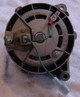
First, we'll describe the disassembly of the alternator. Begin by removing the two screws and one nut that secure the brush pack:
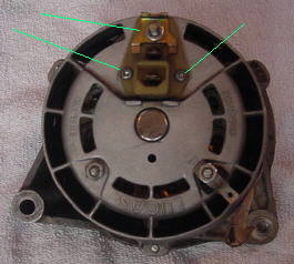
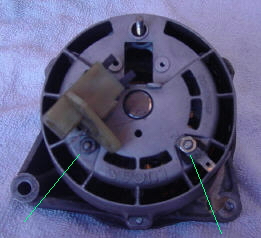
The brush pack comes out as a unit. Note that the plastic body of the brush pack also acts as an insulator for the B+ output of the alternator. Whey you begin to reassemble, be very, very careful that the B+ stud is insulated! Continue disassembly by removing the other two nuts on the rear cover. Next, turn the unit over and remove the three long screws that hold the case together:
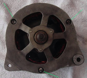
We haven't shown the removal of the pulley and fan: this is a simple matter of removing one nut. The pulley is keyed to the shaft: the Woodruff key can be removed or left in place. Remove the collar that covers the front bearing: it should just lift off. The alternator can now be separated into three pieces. You may need to give it a few taps with a hammer to get it apart:
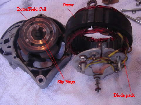
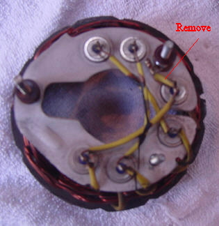
The rotor will not separate from the front bearing without a press: leave it assembled in the front of the case, unless you intend to change the bearings. Now would be a good opportunity to clean the slip rings. They can be lightly polished with a bit of fine sandpaper. The diode pack is held to the front of the stator with three wires, do not remove them. We'll work with the diode pack in place. The next step is to remove the wire which connects to the AL post:
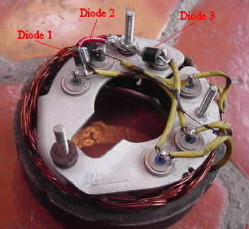
Since the field coil draws about 4 amps maximum, we are going to use three 6 amp diodes. This will give a good margin of safety. Adequate diodes are available from Radio Shack or Digikey. The three diodes will simply connect between each of the three field coil wires and the AL post. The positive terminal of each diode must terminate on the post. It's also important that the diodes be oriented in such a way as to allow the assembly to fit back into the case without shorting: this can result in a difficult layout. As a result, it's a bit hard to see the new diodes in the final assembly:
When we get the unit assembled and running, the AL lead will now be supplying 14.3 volts DC, rather than 7.5 volts of AC. Check to make sure nothing is shorted out. Reassemble the alternator, making sure all parts are put in the correct place, especially the insulators. The alternator should turn freely when you are done. It's especially important to make sure that neither the B+ stud nor the AL stud are shorted to the case. We're now ready to rewire the charging circuit. A few simple rearrangements of the wiring harness are required, shown in red and green on the illustration:
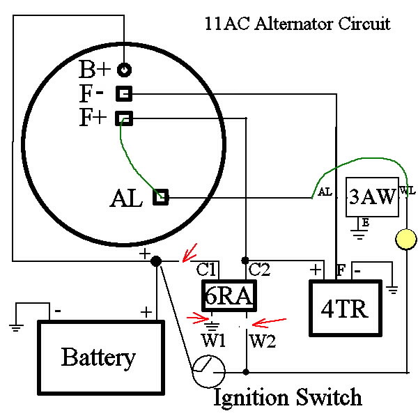
The wiring changes affect the alternator harness, the 6RA harness, and the 3AW harness. First, the AL lead on the alternator must be jumpered to the F+ lead. This will cause the alternator to be self-energized by the trio, rather than powered by the battery. Accomplish this with a pigtail, as illustrated. The wiring can be 16 or even 18 gauge, as it only has to carry about 4 amps:
The Brown/Purple wire from the harness will now plug into the disconnect on the green wire, rather than directly into the alternator. The Brown/Yellow wire will still connect to the AL terminal. The other alternator wires connect to their normal terminations.
Next, the alternator relay will be disabled by removing the three leads as illustrated. The fourth lead will remain, since it acts as a junction between the alternator and the regulator. The unplugged wires will be White, Black, and Brown/Red. Tape them off to prevent shorts. The alternator relay can be found on the left mudguard, just behind the battery. There are up to three relays in this location: the top one is the horn relay, the next down is the alternator relay, the bottom one is for Air Conditioning.
The final step is to connect the AL lead directly to the indicator light. This can be done with a short jumper at the 3AW relay. Simply unplug the Brown/Yellow and the Brown/Black wires, and connect them with a pigtail, making sure everything is insulated. The 3AW can remain in place, but is now out of the circuit.
To really gild the lily, you can install a 300 ohm resistor in parallel with the indictor light. Since the indicator light is now an active part of the charging circuit, a blown bulb will keep the alternator from working. By installing a parallel resistor, you create a fail-safe.
That's about it.
Copyright © 2003
CoolCat Express Corp. All Rights Reserved.