 |
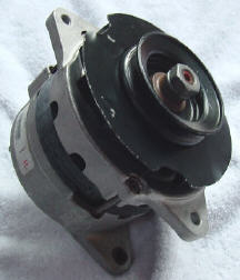
| 1983-1985 Honda Prelude Alternator is a dead ringer for a Series II E-Type Lucas alternator. Comes complete with CCW fan, pulley and baffle. |
When I was first told that the Series II and III E-Types required counter clockwise alternators, I was reminded of an old Boy Scout joke. On the first night of camp, a novice scout would be told to hike down to the next camp and ask to borrow a left handed poker shifter. After hiking a couple of miles, he'd be told there were no spare poker shifters, and would be sent a couple of miles to the next camp. Eventually, he'd be told that there was no such thing as a poker shifter, left or right, and would have to walk back feeling totally duped.
|
| 1983-1985 Honda Prelude Alternator is a dead ringer for a Series II E-Type Lucas alternator. Comes complete with CCW fan, pulley and baffle. |
Alternators can't be handed, since they generate alternating current. There's always 180 degrees of + and 180 degrees of - for each phase, and the diodes sort out everything correctly no matter which way it rotates. As it turns out, the difference isn't in the alternator itself, it's in the way the alternator is cooled.
Automotive alternators are designed with the diodes located in the rear
(not the pulley end). The reason is that semiconductors can be damaged
by heat, and there's more room in the back for heat sinks and such. To
ensure proper cooling, the fan is usually mounted near the pulley, and
it's designed to pull air from back to front, so that the cool air hits
the critical diodes first. If you simply turn an alternator around backwards
(pulley facing the engine), it will spin counter clockwise, and the fan
will push air from front to back. A 60 amp alternator produces about as
much heat as three light bulbs, so the air hitting the diodes would be
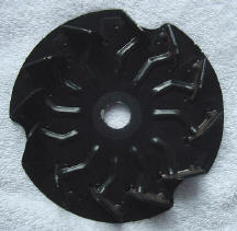
hot. Series II and III E-Types had reverse mounted alternators. To accommodate
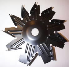
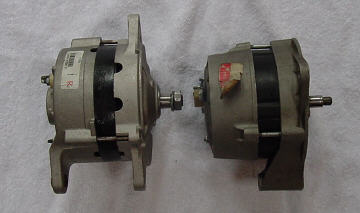
this, the fans are designed to rotate counter clockwise. Here's a comparison
of CW and CCW fans:
 |
 |
|
Note: Blades Point Left |
Note: Blades Point Right |
Owners of Series II
cars with "reversed" alternators can replace their Lucas alternator with
a Nippondenso alternator from a 1983-1987 Honda Prelude 1.8L, Lester#14761.
This alternator puts out 60Amps, and it comes with a CCW rotation fan and
single pulley! It will work with your 4TR voltage regulator, and the 3AW
warning light relay. These notes relate to the early reversed 40A Lucas
alternator, as used on '68-'69 E-Types. Replacement of the later Lucas
60A, or the Series III Butec alternators should be similar, but will require
fabrication of somewhat different adapters.
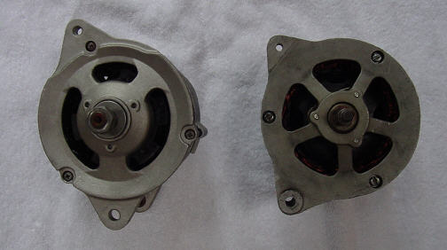 |
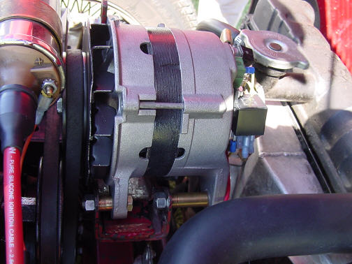
| One of the issues with the Series II alternator is that it's mounted very high in the engine bay. To clear the bonnet, the tensioning lug is located at ten o'clock. The Nippondenso has it's tensioning lug at 11 o'clock, which still allows enough room to clear the bonnet. |
 |
| The Nippondenso mounts with a 3" double foot. The Lucas mounts with a single 2" lug. It's easy enough to adapt the Nippondenso to the Lucas mount. |
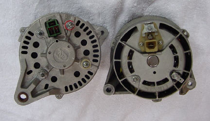 |
| Wiring plans are similar. The Nippondenso field is internally powered (see discussion). |
The Nippondenso alternator has a very similar back face to the Lucas. It has a B+ and F- connection. It has a reference ground connection (E), and it has a connection (P) which is similar to the AL lead on the Lucas alternator. Actually, the P lead is used by the (more sophisticated) Prelude voltage regulator to sense load. Without getting too complicated, it feeds a modified single phase of AC. From the viewpoint of the 3AW relay, it's an AL lead. Naturally, we recommend replacing your 3AW with one of our solid state units.
The Field coil in the Nippondenso alternator is internally wired to the B+ terminal, as a result there has to be some provision for disconnecting the F- lead when the ignition is turned off. This wouldn't be a complication if the Lucas 4TR regulator wasn't, shall we say, inadequate. The Lucas 4TR has a nasty habit of remaining connected to ground when it's unpowered. A relay has to be added to control the field circuit, or there would always be a 2 amp drain to ground when the engine is switched off. Actually, I ended up using a cheap Bosch relay, bolted right to the back of the alternator. We'll see how well that works.
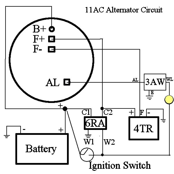
The original and modified
circuits look like this:
 |
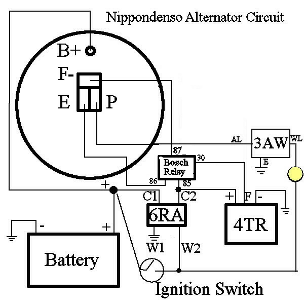 |
| Nippondenso Alternator requires an extra relay to disconnect the field circuit. | |
The physical installation
of the alternator is straightforward, although some light machine work
is needed to make it work. Since the 11AC has a single foot, two spacers
need to be fabricated to attach the alternator to the bracket. Simply cut
these out of 3/8" pipe, available in any plumbing shop. One spacer is .49"
long, the other is 1.46". Two bolts, rather than one, are used to secure
the alternator to the mount. These are pictured below:
 |
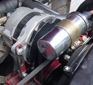
| Note:
- Spacers fabricated from brass plumbing pipe. - Bosch relay bolted directly to rear of case, used to isolate field. The relay could be relocated for more stock appearance. |
Because the Nippondenso
tensioning ear is located at 11 o'clock, the adjustment arm has to be relocated.
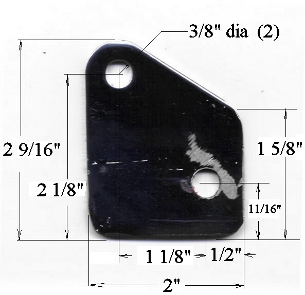
This is done with a simple adapter, which can be fabricated out of a piece
of 3/16" thick mild steel scrap. Click
here to get dimensions for this adapter plate. It may take some fiddling
to get the size and shape of the various adapter bits just right for a
different car.
 |
| Note:
Tensioning arm relocated with fabricated steel plate at bottom. The arm can't extend too high, or it will foul the bonnet. Click here for dimensions of adapter plate. |
The Prelude pulley
is a tad too large. As a result, the stock belt was slightly short, but
a cooperative parts store was able to fit up one that is just right. There
are many 17mm ID pulleys available, I may try a smaller one.
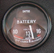 |
| Getting a charge out of my new alternator. |
Copyright © 2004
CoolCat Express Corp. All Rights Reserved.