Crankcase Ventilation System
The
valve covers on Mercedes 60x engines hold a bit of a mystery. The crankcase
breather connects directly to the turbo inlet. There is always negative
pressure in the turbo inlet for reasons that I won't go into here. (For
those who find it counterintuitive that there be vacuum at that point,
just take it on faith.) Inside the valve cover there is a hidden valve
which prevents the turbo from sucking oil out of the engine, similar to
the PCV valve in a gas engine. The valve is not designed to be serviced
and it's function is obscure, but it sometimes creates a crisis when the
turbo starts blowing oil into the intake manifold. I have sacrificed a
spare valve cover to determine exactly how this system was intended to
work, how it can be tested, and maybe how it can be repaired.
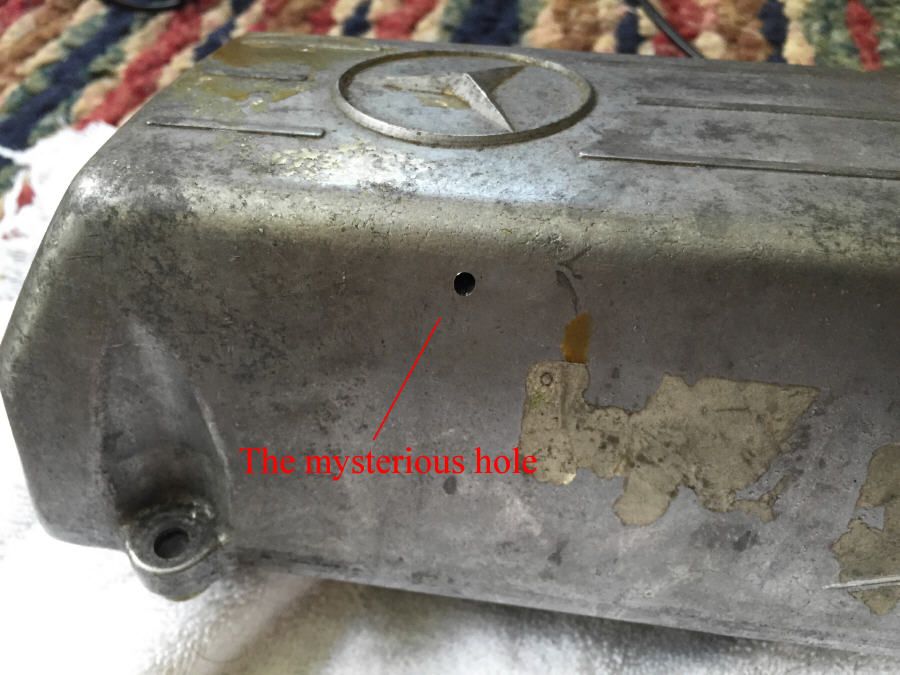
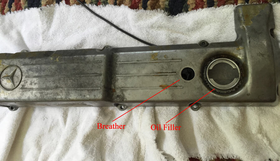
The quick
tour... on the outside of the valve cover there is a tiny hole, easily
overlooked. This hole is critical to the functioning of the entire system
as we will see. If it's plugged, the engine may run poorly, and oil will
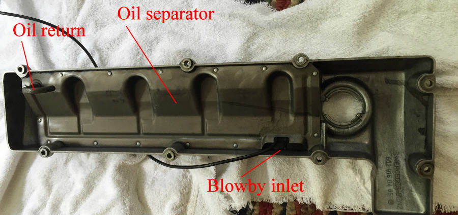
be sucked into the turbo. More about this later. Inside the valve cover
is an oil separator which is supposed to allow oil to settle out of the
blowby gas and reenter the engine. Blowby gasses enter through the rather
large inlet on the front left of the valve cover, flow through the separator
from front to back and then enter to breather tube through the unseen separator
valve. Oil returns through the tube at the rear of the cover. The mechanism
is a bit convoluted, but all is about to be revealed.
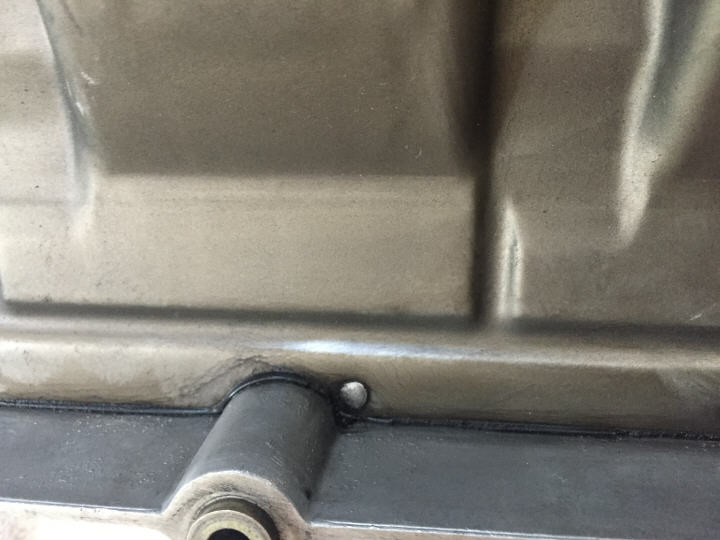
This is why this part is so mysterious. The separator is riveted to the underside of the valve cover. The rivets were probably installed when the cover was hot and really beaten into place. This design prevents the fasteners from vibrating out (very important, since they are deep inside the engine). But it also prevents them from being removed in any non-destructive way. Because of this, the valve cover has to be considered unserviceable. Also note the black bead running along the edge of the separator. This appears to be a gasket, not sure if it's a real gasket or formed in place. There are folks who speculate that their oil ingestion problems are caused by leakage from this gasket, and they apply sealant here. Don't do it. It's unnecessary, as any oil leakage here would just drain back into the engine without interfering with the operation of the separator. That's actually a good thing. And given the force that was used to install the rivets, the cover protects the important parts of the gasket pretty much forever. A bead of sealant on the outside of the separator can fail and drop into the engine, causing a real problem. So don't do it. I had
to cut the tops off the rivets with a chisel to get inside. Clearly, not
a reversible procedure. So anything that follows is information possibly
of diagnostic value, but certainly not a repair procedure.
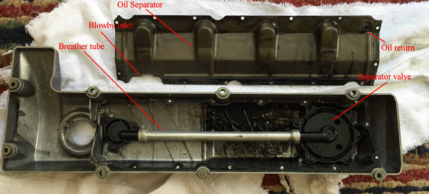
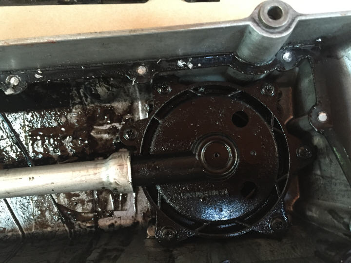
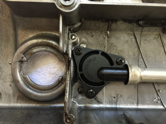
And now
we can see the mysterious insides. The most important feature is a separator
valve which connects to the vent hole by a breather tube. One of the many
mysteries here is why so much oil ends up gathered around the valve,. As
you can see, the rear half of the cover is thick with it. More about that
in a bit. Let's see how the valve is constructed.
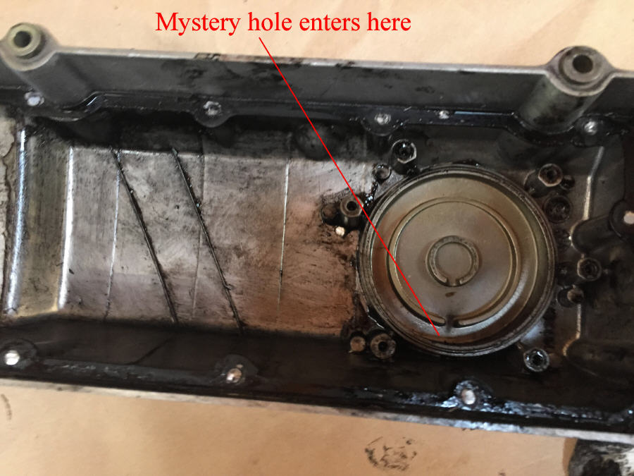
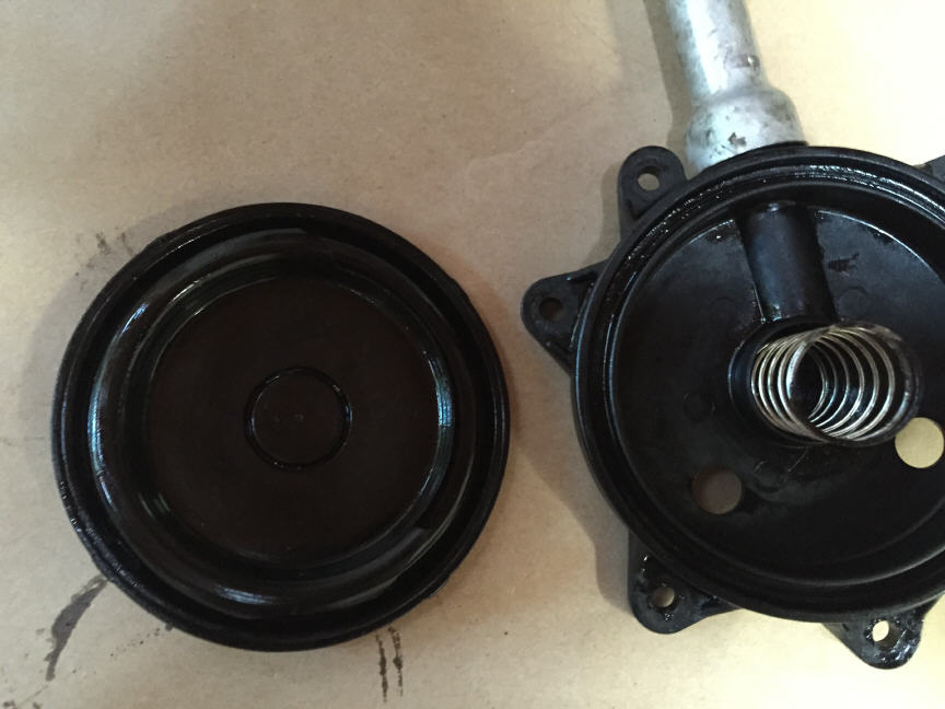
The separator
valve screws into the top of the valve cover, directly underneath the Mercedes
"star'. It's a type of PCV valve, called a "Type II PCV". There is a rubber
diaphragm sandwiched between the valve and the cover. The bottom of the
diaphragm is exposed to blowby pressure, because it faces inwards. The
top of the diaphragm is exposed to normal atmospheric pressure, because
the previously mentioned tiny hole enters the valve cover here. This allows
the diaphragm to flex in and out as blowby pressure increases or decreases.
This is why the hole must be clear. Don't use chemical sprays to clean
it, either, as the rubber diaphragm may be damaged.
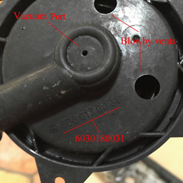
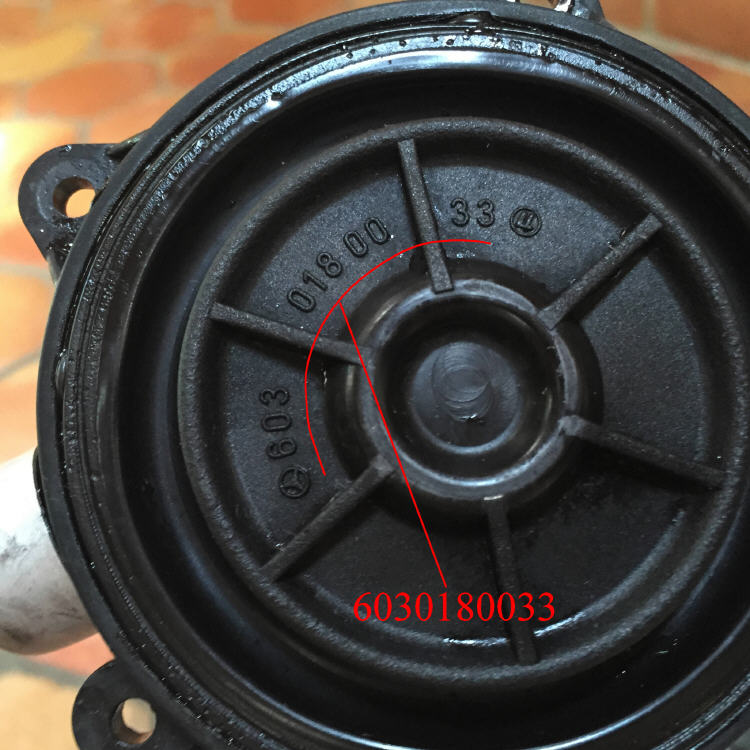
The bottom of the separator valve has two holes to allow the passage of blowby gasses. These are the only paths for blowby to leave the engine. The separator valve has a part number, but if we flip it over, the diaphragm which at first appears integral has a different part number. This diaphragm looks ok, but it's lost it's flexibility. It's doing something, but not working as intended.
The diaphragm separated from the valve body. The turbo draws a vacuum in the crankcase (please don't question this, it really happens). As it does, air pressure forces the diaphragm down against the spring, closing off the breather passage. A bit of vacuum bleeds through the vacuum port when the diaphagm is closed, maintaining a bit of negative pressure in the crankcase. When the engine is producing blowby pressure, this offsets turbo vacuum and forces the valve open. Simple. Except that sealed inside the valve cover is a decaying diaphragm that can't be sourced, and you end up with oil being blown into the intake manifold
The breather pipe connects the valve with the breather outlet with viton o-rings at the junctions. 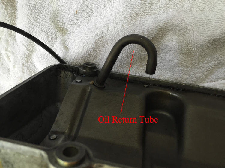 Could this be the reason the turbo gets oiled? Any oil captured by the separator goes back to the engine through this return tube. The tube is located directly under the separator valve, and traps oil because of it's shape. There must be some reason for this design, other than to encourage oil to be picked up by the turbo. It's
very hard to diagnose problems with this system. This scrap cover seemed
fine, but the diaphragm had lost a lot of flexibility. Even if the
problem could be diagnosed without destroying the cover, there's no solution
other than a new (very expensive) valve cover.
|
Copyright © 2015 CoolCat Express Corp