 |
|
 |
|
|
|
|
|
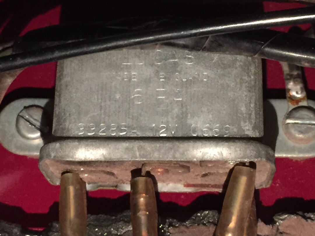
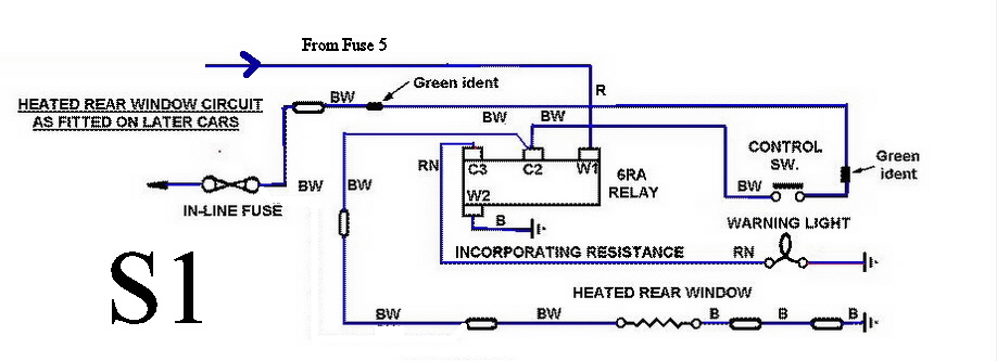
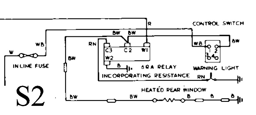
This is the circuit used for the rear window defogger in S1.5 and S2 cars. Its operation is somewhat obscure. You would think the relay is used to switch the heating element, but no. What it does is dim the yellow indicator light. Here's how it works: Daylight operation: the control switch (on the center dash panel) directly switches power from the inline fuse to the heated rear window element. This relay is normally closed and the winding isn't powered, so C2 and C3 have continuity. As a result, the control switch is also supplying a full 12V to the indicator light. Nighttime operation: As before, the control switch directly switches power from the inline fuse to the heated rear element. But when the sidelights are on, the relay winding (W1) gets power from fuse 5. Since this is an NC relay, it opens. And then a bit of magic happens. Internal to the relay, there is a resistor that connects C2 and C3. As a result, voltage to the indicator bulb is reduced, and it dims. It's confusing because you can't see the resistor on the schematic. This
relay is Lucas#33285a, this is a Normally Closed relay, with resistance.
A conventional relay cannot substitute for this special part, nor should
one of these be used in other applications.
Test procedure: 1) Disconnect the wires from all four relay terminals. Measure resistance across C2/C3. It should measure less than 1 ohm, the closer to zero the better. 2) Reconnect the wires to W1 and W2. Turn the headlights on. Again, measure resistance across C2/C3. It should now measure 50 ohms, with a 10% tolerance. 3) If both tests are ok, reconnect all the wiring, the relay is good. |